User Guide
Introduction to BENCHLAB

BENCHLAB is a cutting-edge, compact, real-time system telemetry solution engineered for PC DIY enthusiasts brought to you by Open Benchtable and ElmorLabs.
It allows you to effortlessly monitor critical system metrics, including temperature, power usage, and voltage levels. You can also manage system fan speeds. The telemetry data is displayed in the BENCHLAB software, and you can log and export data to a file or to HWiNFO.
BENCHLAB empowers PC DIY enthusiasts to make informed decisions when fine-tuning the system's performance. It helps identify potential hardware issues before they escalate and helps optimize any hardware configurations seamlessly. Its intuitive design makes it a must-have tool for seasoned overclockers and PC DIY enthusiasts, simplifying the complexities of system telemetry.
Installing the BENCHLAB Hardware
Installing the BENCHLAB hardware is very simple and straightforward. Since it’s designed to fit neatly with the Open Benchtable, we’ll use it to explain the step-by-step installation process.
BENCHLAB hardware installation step-by-step instructions
Set up the Open Benchtable
- Install the power supply and attach the power supply cables. You can also mount the storage drives.
- Mount the BENCHLAB standoffs on the Open Benchtable
- Place the BENCHLAB PCB on top of the standoffs
- Mount the Open Benchtable standoffs on top of the BENCHLAB to secure the BENCHLAB
- Connect both the input and output power supply cables to the BENCHLAB
- Install the motherboard on top of the BENCHLAB
- Connect the power supply cables to the motherboard. Additionally, you can now also attach the RGB cable, fan cables, etc to the BENCHLAB.
Installing the BENCHLAB Software
The BENCHLAB software is also easy to install.
- Download the software from our Github page: https://github.com/BenchLab-io
- Unzip the files in a new folder
- Double-click the executable to start the software
- Make sure the BENCHLAB is connected to the system where the software is installed
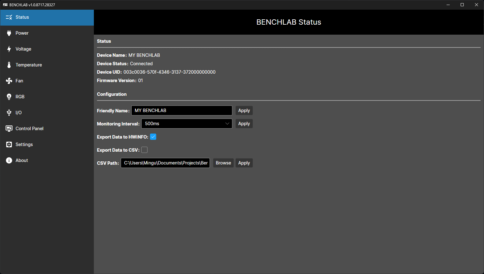
- Upon opening the software, you should see that the BENCHLAB device is connected
Getting Started with BENCHLAB
The BENCHLAB hardware and software provides a wide range of system telemetry. In the coming sections we go over each of the telemetry functions in detail.
Power Measurement
BENCHLAB ensures complete visibility over your system's power consumption by providing comprehensive power measurement for 4+4-pin EPS (x2), 24-pin ATX (x1), 6+2-pin PCIE (x3), and 12VHPWR (2x) connectors.
Connect the power supply cables to the following input power connectors on the BENCHLAB:
- PSU_CPU1 & PSU_CPU2 = 4+4-pin EPS
- PSU_ATX24 = 24-pin ATX
- PSU_GPU1, PSU_GPU2, & PSU_GPU3 = 6+2-pin PCIE
- PSU_HPWR1 & PSU_HPWR2 = 12+4-pin 12VHPWR
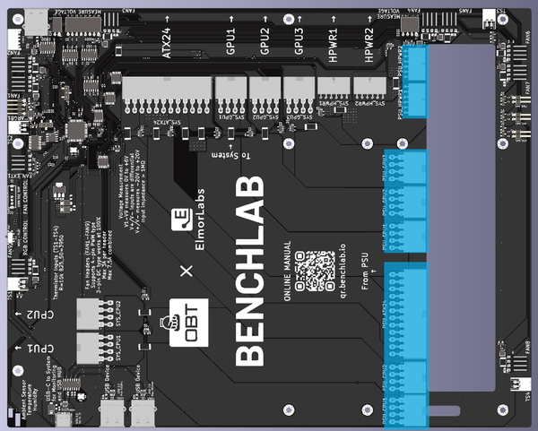
- SYS_CPU1 & SYS_CPU2 = 4+4-pin EPS
- SYS_ATX24 = 24-pin ATX
- SYS_GPU1, SYS_GPU2, & SYS_GPU3 = 6+2-pin PCIE
- SYS_HPWR1 & SYS_HPWR2 = 12+4-pin 12VHPWR

Do not use any other cable (e.g. modular PSU cables) to connect the BENCHLAB power to the system as it may result in irreversible damage!
Voltage Measurement
The BENCHLAB voltage measurement system features 1x ±18V differential and 12x 0-4V single-ended channels which enables you to keep a close eye on voltage fluctuations, guaranteeing stable and secure operation.
V1 to V8 are located next to the USB Type-A port in the upper right corner of the PCB. They are intended to be used for motherboard voltage measurement. They are single-ended inputs that measure 0V to 4V.

V9 to V12 are located next to the 12VHPR connectors in the lower right corner of the PCB. They are intended to be used for graphics card voltage measurement. They are single-ended inputs that measure 0V to 4V.

V+/V- located next to the USB Type-A port in the upper right corner of the PCB. These are the inputs for the differential voltage measurement which ranges from -18V to +18V.

Temperature Measurement
To keep track of the thermal operating conditions, BENCHLAB's advanced temperature measurement functionality includes an embedded ambient temperature and humidity sensor, as well as support for four external temperature sensors.
The ambient temperature and humidity sensor are located at the back of the PCB in the upper right corner.

TS1 to TS4 can be found around the edge of the PCB. These are thermistor cable inputs intended for external temperature measurements, such as the water temperature.

Fan Control
The conveniently integrated fan controller supports up to 9x 4-pin PWM fans (FAN1 to FAN9) whose curves can be mapped to any of the temperature sensors via the BENCHLAB software.

In case you don't want to use the software, you can also control the fans using a physical switch (SW1).

Connect FAN_EXT1 to the a fan connector on your motherboard to control the fans connected to the BENCHLAB via the motherboard.

RGB Control
The BENCHLAB has 30x addressable RGB (ARGB) LEDs fitted on the backside of the PCB which provides you with a stunning, customizable visual backdrop. You can control the RGB pattern either by the BENCHLAB software or by connecting it to a motherboard via the RGB connector.

You can disable the RGB function using SW2.

I/O Devices
BENCHLAB also features several I/O connections.
USB1 is the USB 2.0 Type-C connector to the system for using the BENCHLAB software.

USB2, USB3, and USB4 are USB 2.0 Type-A connectors and can be used to connect any kind of peripheral like keyboard or mouse.The devices connect to the same system that's connected to the USB Type-C.

Three 2-pin connects can be used for specialty functions such as power on and reset.

Last but not least, an expansion connector (CTRL1) is reserved for future functionality.

Logging and Exporting Telemetry
BENCHLAB currently supports two main methods of logging and exporting the telemetry data: logging to a CSV file or exporting to HWiNFO.
To export the telemetry data to HWiNFO, simply check the box next to 'Export Data to HWiNFO' on the Status tab. This option is checked by default.
To log the telemetry to a CSV file, simply check the box next to 'Export Data to CSV' on the Status tab. BENCHLAB will write the telemetry data to the file in the designated folder mentioned in CSV Path.

There are two ways to select which data is exported to HWiNFO or logged in the CSV file.
First, you can manage the telemetry export on the Settings > Sensors tab. Simply click on the icon in the HWiNFO and CSV column to enable or disable telemetry export.

Second, you can also enable/disable export by clicking the configure icon on every monitoring chart.

There are quite a few BENCHLAB telemetry data points available, so your HWiNFO might look full.

Technical Specifications
Below you can find a detailed overview of the technical specifications of all the connections on the BENCHLAB.
Power Measurement
|
Connector |
Type |
Max Continuous Power |
|
CPU1 CPU2 |
4 or 8-pin EPS |
32A @ 12V (384W) |
|
ATX24 |
20 or 24-pin ATX |
20A @ 3.3V (66W) 20A @ 5V (100W) 15A @ 12V (180W) |
|
GPU1 GPU2 GPU3 |
6 or 8-pin PCIE |
24A @ 12V (288W) |
|
HPWR1 HPWR2 |
12+4-pin 12VHPWR |
60A @ 12V (720W) |
Voltage Measurement
|
Connector |
Type |
Voltage Range |
|
V1 to V12 |
>1MΩ impedance single-ended |
0V to 4V |
|
V+ V- |
≥1MΩ impedance differential |
-18V to +18V |
Temperature Measurement
|
Connector |
R value |
B value |
|
TS1 to TS4 |
10K @ 25°C |
3950K (25°C - 50°C) |
Fan Headers
|
Connector |
Type |
Max Continuous Power |
|
FAN1 to FAN9 |
4-pin PWM |
3A @ 12V (36W) per connector 7.5A @ 12V (90W) combined |
I/O Connectors
|
Connector |
Type |
Max Continuous Power |
|
ARGB |
3-pin |
2A @ 5V (10W) |
|
USB1 |
Type-C |
2A @ 5V (10W) |
|
USB2 to USB4 |
Type-A |
500mA @ 5V (2.5W) |